POWER-GENERATING SHOCK ABSORBER (PGSA)
The Power-Generating Shock Absorber (PGSA) uses energy that would be otherwise lost as heat to generate electricity.
A conventional automotive shock absorber dampens suspension movement to produce a controlled action that keeps the tire firmly on the road. This is done by converting the kinetic energy into heat energy, which is then absorbed by the shock’s oil.
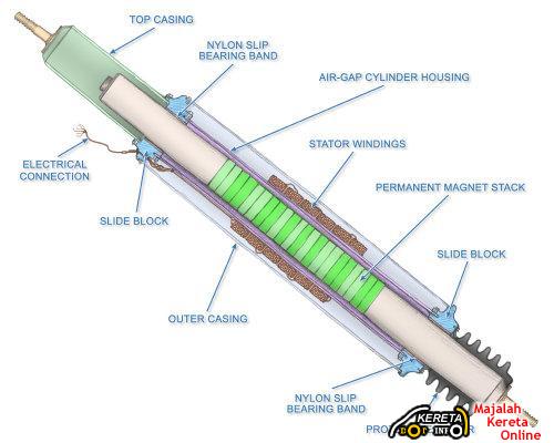
The Power-Generating Shock Absorber (PGSA) converts this kinetic energy into electricity instead of heat through the use of a Linear Motion Electromagnetic System (LMES). The LMES uses a dense permanent magnet stack embedded in the main piston, a switchable series of stator coil windings, a rectifier, and an electronic control system to manage the varying electrical output and dampening load.
The bottom shaft of the PGSA mounts to the moving suspension member and forces the magnet stack to reciprocate within the annular array of stator windings, producing alternating current electricity. That electricity is then converted into direct current through a full-wave rectifier and stored in the vehicle’s batteries.
The electricity generated by each PGSA can then be combined with electricity from other power generation systems (e.g. regenerative braking) and stored in the vehicle’s batteries.
Plug-and-Play
The PGSA is the same basic size and shape, and mounts in the same way, as a standard shock absorber or strut cartridge.
BELOW ARE SOME INFORMATION THAT WE GET FROM THE PROJECT DESCRIPTION BY JONATHAN BANKSTON, YAVUS MENTES AND ALEX RUDERMAN. HOPE THAT YOU GUYS CAN UNDERSTAND HOW IT WORKS.
Fig.1 – Example Of Power Generating Shock Absorber.
The mechatronic system we have chosen to model is an Power-Generating Shock Absorber (PGSA) acting on an automotive chassis. The shock absorber will be used in conjunction with a spring to simulate one of the four suspension system of an automobile. When designing an automotive suspension system the key is to balance the ride of the automobile. More specifically, the suspension is meant to absorb the effects of an uneven driving surface and tilt/sway of the car. However, excess energy loss occurs due to resistance in the damper fluid and compression of the spring. The PGSA converts kinetic energy into electricity through the use of a Linear Motion Electromagnetic System (LMES). As shown in the Figure 1, the absorber consists of a damper with permanent magnet stack that slide in and out of stator windings connected to two sliding blocks inside the damper casing.
Fig.2 – Detailed view of suspension (PGSA + Spring) model.
Our model of a PGSA (Figure 2) uses a modified eMF. The eMF was converted for translational motion and installed opposite of the traditional application. A power sensor with an integrator measures the energy generated by the reverse linear motor. The model in Figure 2 is the strut-tower setup, so a spring was included to complete the model.
Fig.3 – Model Of Entire Car Including Suspension And Tyre.
To accurately test our PGSA, we utilize four of the shock absorbers in a model of a traditional four-wheeled car (Figure 3). The electrical energy generated is the sum of the output from all four PGSAs. The ride quality in the car is characterized by the maximum vertical acceleration, taken by an accelerometer. The cost of the PGSA is calculated outside of Dymola in an Excel Spreadsheet. These objectives were analyzed in ModelCenter. These links between the Excel spreadsheet, the Dymola model, and the Latin Hypercube Sampling analysis are shown in Figure 4.
Fig.4 – ModelCenter Model for analyzing car suspension utilizing PGSA
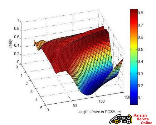
Fig.5 – Surface Plot of Utility of PGSA for cross-sectional area = 7.31 × 10⁻⁷ m2
Our use of the optimization process helped our design variables to converge to an optimal design alternative. The most valuable combination of design variables is a magnetic field of 0.556 Tesla, a wire length of 268.49 meters, and a cross-sectional area of 1.176 × 10⁻⁶ m2. The corresponding utility value for the nondeterministic case is 0.8493 which is slightly higher than that of our optimal design alternative in the deterministic case.
Based on the overall design process undertaken, the optimal values were acceptable for the assumptions that were made. We believe that a more accurate evaluation of the system could be made by expanding the number of controllable design variables and taking into account other uncertain variables that were not considered. Due to the lack of high level knowledge and attention required in this course and the short period of time, the beginning of the problem selection and analysis began a rode of a number of large assumptions that limited the possibilities of a truly accurate design. Even though the design space was limited from the beginning, the overall process was followed and internalized by all of us relating in a comparable increase in knowledge of the work necessary to solve a design problem under uncertainty using the modeling and simulation tools from this course.


Jom komen!